|
All
content
copyright © 1995-2003
RedShirtImaging, LLC.
Web site Design by
Elizabeth
Nephew
|
|
|
|
Before installing
the system, please read the important precautions listed on the Hardware Limitations web page.
|
Unpacking
1. Check for dents or damage to all packing
boxes. If damaged, please make a record.
2. Unpack all components. You should find the
following:
o Diode
array
o Power
supply
o Interface
panel
o Computer
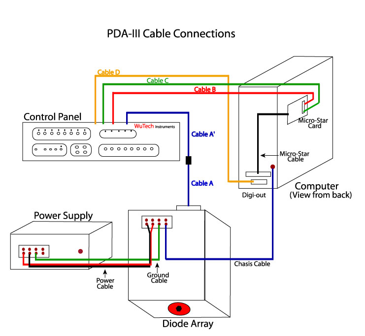
 SCHEMATIC
DIAGRAM of the NeuroPDA-III System SCHEMATIC
DIAGRAM of the NeuroPDA-III System
(thumbnail shown at right)
|
|
Checking the Power
Supply Unit
a) Line voltage. Make sure your line voltage (110V for US and Japan, 220V
for European users) matches the label on the power supply unit.
If not, do not turn on the power supply. Contact immediately WuTech (wuj@georgetown.edu)
or your dealer.
b)
Output voltage. Connect the power supply to
the wall plug and the power supply
"chassis" to the main ground in your laboratory. Turn on the power
supply (the array should NOT be connected to the power supply at this
point). The two indicator lights on the power supply should be on. Use
a voltmeter to measure the output voltages of
the power supply. These should be +15V (red to green) and -14.2V (black
to green).
c)
Short circuit protection. Turn the
power supply off and use a piece of wire to short the +15v to the
ground connector. Now turn on the power supply. The indicator light for
the +15V should not turn on but the
light for the -14.2V should light normally. Remove the wire - the +15V
light should turn on, indicating the over current protection is working
properly. Repeat the test for the -14.2V supply (by shorting the -14.2V
to ground). If the indicator lights do
not turn back on after the shorting wire is removed, a fuse (inside the
power supply) may have blown. Contact WuTech
or your dealer.
Checking
the diode array
a) Mount the diode array on microscope. Before mounting remove the protection cover from the
array aperture. The diode array can be mounted on the image port of a
microscope/macroscope via a "C" mount. If
the image port is not mechanically strong, or if the array is mounted
horizontally, add mechanical support
for the array. (See also Mounting the NeuroPDA-III on a microscope.) If you opt not to mount the array at this
point, lay it on a table with the connector side up and uncover the
aperture.
b) Connect the array to the power supply. Make sure the power supply unit
is OFF. Identify the speaker wires leading out of the array,
labeled "Power Cable" and "Ground Cable" and connect them to the power
supply unit: The red connector (of the red speaker wire) goes to the
+15V connector on the power supply; The black connector (marked with a
black tape, on the uncolored speaker wire) goes to the -14V. The Ground
Cable (speaker wire with green or blue connector) connects to the
ground connector on the power supply unit. Do not turn on the
power supply yet. 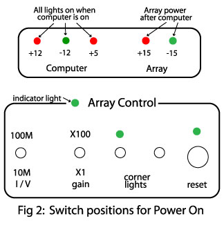
c) Connect the array
control cable to the control panel. Connect
"Cable A" (a 40 lead flat cable) from the array and "Cable A'" leading
out of the control panel to each other. Set the "Array Control"
switches on the panel to: 10Mohm, X1 (See
figure 2).
d) Power on the array. Turn on
the power while watching the +/-15V indicator lights on the power unit.
These should light normally. The green light on the Array Control
section of the panel should also light. If any of these lights do not
turn on or look dim, turn off the power supply and contact Wutech or your dealer.
Never
power the array without connecting it to the Array Control.
Always
set the array gains to 10Mohm,X1 when
turning the power on/off (See
figure 2).
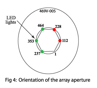
e) Corner lights on the array.
Turn on the "corner light" switch on the control panel and look at the
array aperture. The fiber optics aperture is surrounded by red and
green light guides. These lights are there to help orient the optical
detector map. The orientation of the array is shown in Figure 4.
f)
Testing the diode array. Connect one of the
"Optical Output" channels (located on the center section of the control
panel) to an oscilloscope (vertical gain = .5V/div). While the array
power is on, set the array controls to 10M, X100. Provide a light
signal (see below) to the array aperture and watch the output signal on
the oscilloscope: the voltage change should correlate with the light
intensity modulation.
If the array is mounted on a microscope, use the microscope light as
the signal: Adjust the light level to be comfortable to the eye and
approximately eve across the field of view. Switch the light from the
eyepiece to the array. Use a piece of rigid paper (like an index card)
to temporarily block the light (wave the card through the light path
below the condenser). If you don't see a signal,
readjust the light so it is not too bright to the eye, then
switch back the light from the eyepiece to the array . If the array is
not mounted on the microscope, use the room lights to check it. Room
light will usually provide a 120 Hz
fluctuation. Covering/uncovering the array aperture should
change the amplitude of this modulation as seen on the oscilloscope.
Different combinations of gains provide different sensitivity to the
light. The two switches on the left of the "array control" panel (Figure 2) determine the the
first and second stage gains. Changing the gain switch from x1 to x100
results in a 100 times larger output signal (2nd stage). Changing the
first stage gain (I / V switch) from 10M to 100M, the array sensitivity
grows 10 times. Note that at normal room light, using 100M for the
first stage may saturate the array (flat line, no signal). This is
normal and will not damage the array.
After testing the array, turn off the array power and proceed to the
next stage.
Checking the
computer and software.
a) Connecting the control panel to the computer. Turn off the computer. Identify Cables B and C from the control
panel (Figure
1) and connect them to the MicroStar
Card. Connect the MicroStar card to the
computer via the MicroStar Cable (Figure
1). At this time do not connect other cables from the control panel
and leave the array power off. Now boot up the computer and watch the
power indicator lights go on the control panel (Figure
2). All three lights for the computer power should be on,
indicating that Cable B and C are connected correctly and the panel is
powered. If none of the lights are on, check the connection of the MicroStar cable (Figure
1). If any of the lights is off, turn off the computer and check
the connections of the cables, then try again. If any of the indicators
fail to lit contact WuTech.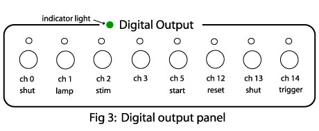
Identify Cable D of the control panel and connect it to the "Digi-out" port on
the back of the computer. Cable D connector is a female 25 pin "D"
connector, similar to the 2nd serial port on some computers. The "Digi-out" port is usually clearly marked.
Alternatively it is located next to the MicroStar
A/D convertor connector. If Cable D is correctly connected and the
computer is on the green indicator light on the digital output section
of the control panel (Figure
3) should lit.
b)
Testing the digital output. Run the Neuroplex software and take data (See below). The lights on each Digital output
channel should blink indicating execution of the control command.
Briefly, the "lamp" and "shutter" lights will be on for the duration of
acquisition; "reset" will blink once at the beginning of a run and "stim" will blink when the stimulation command is
issued (Figure
3). The time and duration of the "reset" command can be adjusted
with the software, as discussed in the software manual. The expected
blinking indicates the output section is working properly.
 c) Testing the analog input. There are 8 analog inputs channels in the H469-V allowing
for simultaneous recording of eight different electrical signals (electrodes, EEG, EKG, respiration, etc.)
during imaging. The input channel connectors are located on the control
panel. In the software they are labeled 465-472. To test these channels
feed a 1 volt p-p, 40 Hz sine wave into one of the channels (e.g.
#465). Run Neuroplex, taking at least 1024 points per sweep. Display
channel 465 on the left (trace) panel of Neuroplex.
Repeat this for all other analog channels. c) Testing the analog input. There are 8 analog inputs channels in the H469-V allowing
for simultaneous recording of eight different electrical signals (electrodes, EEG, EKG, respiration, etc.)
during imaging. The input channel connectors are located on the control
panel. In the software they are labeled 465-472. To test these channels
feed a 1 volt p-p, 40 Hz sine wave into one of the channels (e.g.
#465). Run Neuroplex, taking at least 1024 points per sweep. Display
channel 465 on the left (trace) panel of Neuroplex.
Repeat this for all other analog channels.
Testing the whole
system.
This is the last and most important step of the installation.
Before this step, both the array and the computer/control panel should
be connected and properly tested (see above). Do not carry out the
whole system test if you found problems during the previous tests.
a) Connecting the
array to the control panel. Turn off the
power to both the computer and the diode array. Identify Cable A from
the array and mate it with Cable A'
from the control panel (see Figure 1).
Connect the "Chassis Cable" from the array to the connector on the
computer chassis.
b)
Power on the whole system.
Always
remember to turn on the computer before turning on the array. The power supply indicators on the control panel (Figure 2) are designed to help the user remember
the "power on" sequence: You can have the computer on without the array
powered up, but never allow a situation where the array is powered and
the computer is off. Also, before turning on the array power, set the
array gain to 10M, X1 (Figure 2).
c)
Testing the system. Run Neuroplex (see Running Neuroplex
below) and acquire data.
d)
Dark Noise. Measure the dark noise using the
fastest acquisition rate. In addition to determining the size of the
dark noise by measuring its RMS value, determine its frequency content
by using FFT option under Trace. There should be little or no line
frequency (or harmonics) noise as well as no increase at high
frequencies (which would indicate oscillations). A flat spectrum is
good.
e) Bad
channels. Illuminate the diodes
approximately evenly. Take data and examine the Page Display screen,
looking for diodes which don't respond or are excessively noisy.
Typical system has 5 or fewer bad channels. If you find more than five
it is possible that the cards in the box are no longer properly seated.
Very carefully remove the top of the diode array and check to see that
no card has shifted. Carefully replace the top of the diode array. (You
can use either the Fudge Array or Omit Array to replace the bad
detectors with data from surrounding detectors or with flat lines).
This is the final step of the
installation. Important hardware limitations can be found in Support
Issues: NeuroPDA-III Hardware
Limitations.
Running Neuroplex:
To
take data use the following procedure:
Click
on the NeuroPlex icon on the desktop to
run the program. When the NeuroPlex window
is opened, use Setup >> New Page and Trace Screen Size to make
the Page and Trace screens have the desired size. Do Acquire >>
Photodiode Array >> Number of Points so that the trace duration
is about 1 sec. Then Go >> OK >> Start to take data.
Mounting the NeuroPDA-III on a microscope.
With
a proper adapter, the NeuroPDA-III can be
mounted on a C-mount port, TV port or any other port with real image.
However, we recommend that it will be mounted on a "simple" port for
maximum light throughput. Most research microscopes provide this kind
of high throughput port. In general, the fewer lenses between the
objective and the fiber optics, the higher the throughput.
On the housing, outside the optical aperture, there are three mounting
holes tapped with 10-32 thread. These three holes fasten three 10-32
screws and a plate (red color) with a C-mount thread on the aperture.
This C-mount thread can be used to interface with most microscopes.
Spaces can be added between the array body and the C-mount plate, in
order to obtain parfocality between the
array and the ocular of the microscope.
Congratulations
and enjoy the new system.
Jiang-young Wu, Ph.D.
WuTech Instruments
2 Oceania Court
Gaithersburg, MD 20877
U.S.A.
Chun Falk, Ph.D.
Lawrence Cohen, Ph.D.
RedShirtImaging, LLC
2 Stoneleigh Road
Fairfield, CT 06825
U.S.A.
|