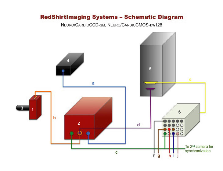
Description: RedShirtImaging, LLC.

Description: NeuroCCD-SM Cooled-CCD Imaging System
Installation


Description: Description: Description: Description: Description: http://www.redshirtimaging.com/support/images/cornerpinkffcfd2_ul.gif

Description: Description: Description: Description: Description: http://www.redshirtimaging.com/support/images/blank.gifDescription: Description: Description: Description: Description: RedShirtImaging Home

Description: Description: Description: Description: Description: http://www.redshirtimaging.com/support/images/cornerpinkffcfd2_ur.gif

Description: Description: Description: Description: Description: http://www.redshirtimaging.com/support/images/blank.gif


  SOFTWARE


Description: Description: Description: Description: Description: http://www.redshirtimaging.com/support/images/x.gif

  NeuroPlex

  Turbo-SM


Description: Description: Description: Description: Description: http://www.redshirtimaging.com/support/images/x.gif

  DownloadDescription: Description: Description: Description: Description: http://www.redshirtimaging.com/support/images/blank.gif


  HARDWARE


  FastCMOS-128X


  NeuroCMOS-DW


  NeuroCCD-SMQ/SMQ-II

Description: Description: Description: Description: Description: http://www.redshirtimaging.com/support/images/icon_reddot.gif SMQ-II Installation

  Description: Description: Description: Description: Description: http://www.redshirtimaging.com/support/images/icon_reddot.gif SM/SMQ Installation

Description: Description: Description: Description: Description: http://www.redshirtimaging.com/support/images/icon_reddot.gif Start-Up Procedure

Description: Description: Description: Description: Description: http://www.redshirtimaging.com/support/images/icon_reddot.gif Warning

Description: Description: Description: Description: Description: http://www.redshirtimaging.com/support/images/icon_reddot.gif Hardware Limitation


  NeuroCCD-SM256


  NeuroPDA-III


  MacroScope-II & -IIa


  Shutter


*****************

Minimizing NoiseDescription: Description: Description: Description: Description: http://www.redshirtimaging.com/support/images/blank.gif


Ask The Expert


*****************


INFORMATION


Description: Description: Description: Description: Description: http://www.redshirtimaging.com/support/images/icon_reddot.gif

Contact Us


Description: Description: Description: Description: Description: http://www.redshirtimaging.com/support/images/icon_reddot.gif

Users


DISTRIBUTORS


Description: Description: Description: Description: Description: http://www.redshirtimaging.com/support/images/icon_reddot.gif

Australia, New Zealand


Description: Description: Description: Description: Description: http://www.redshirtimaging.com/support/images/icon_reddot.gif

British Isles, Benelux, France, Italy, Scandinavia, and Spain


Description: Description: Description: Description: Description: http://www.redshirtimaging.com/support/images/icon_reddot.gif

China, Hong Kong


Description: Description: Description: Description: Description: http://www.redshirtimaging.com/support/images/icon_reddot.gif

Japan


Description: Description: Description: Description: Description: http://www.redshirtimaging.com/support/images/icon_reddot.gif

Switzerland


Description: Description: Description: Description: Description: http://www.redshirtimaging.com/support/images/icon_reddot.gif

Taiwan


Description: Description: Description: Description: Description: RedShirtImaging Home


Description: Description: Description: Description: Description: http://www.redshirtimaging.com/support/images/cornerpinkffcfd2_ll.gif

Description: Description: Description: Description: Description: http://www.redshirtimaging.com/support/images/blank.gif

Description: Description: Description: Description: Description: http://www.redshirtimaging.com/support/images/cornerpinkffcfd2_lr.gif

Description: Description: Description: Description: Description: http://www.redshirtimaging.com/images/x.gif


Description: Backpropagation of action potential in neocortical pyramidal neuron. Measured using NeuroCCD, frame interval .37ms. Provided by Srdjan Antic and Dejan Zecevic, Yale University.

All content
copyright © 1995-2002
RedShirtImaging, LLC.
Website Design by
Elizabeth Nephew


  1. Connect cables for the system following the instructions on the Schematic Diagram for the NeuroCCD-SM shown below.
  2. Connect "Stim" on the Control Box (see below) to your stimulator input trigger.
  3. Connect "Shutter" on the Control Box to your shutter driver.
  4. Connect the "monitor" signal on your stimulator to Input 1 on the Control Box.


Components:

1.

Camera Head.


A high-speed back-illuminated CCD camera which acquires continuous frames at a speed up to 2.0 KHz at 80x80, 3.0KHz at 40x40, and 5.0KHz at 26x26.


2.


Camera Controller


It communicates with the camera and the EDT card inside the computer.

3.


Optical Coupler  


Resizes the image created at the microscope image plane onto the 1.92mm2 CCD chip at a ratio of 10:1. C-mount is provided for standard microscope mounting.

4.


Power Supply


Power supply for the camera.

5.


Computer


The data acquisition unit with an EDT card that communicates with the camera via the controller and a Microstar A-to-D/D-to-A board that simultaneously records up to 8 channels of electrical data and controls the experiment.

6.


Control Panel


The control panel is the central plug-in point for various signals.

1. It sends the trigger signal to the camera via line c.
2. It sends out the control signals from the D-to-A to control the shutter (line i) and the stimulator (line j).
3. It receives electrical signals via the top 8 channels ( ).
4. It sends analogue output signals via the g BNCs.


Connections:

     a - Power supply to camera controller.

b - Cable connecting the camera head and the controller.

c - Clock trigger line from the control panel to camera controller. **

d - Camera controller to EDT board.

     e - Cable connecting Microstar A-to-D/D-to-A board to the control panel.

f - 8 BNC inputs.

g - Analog outputs (See Software Manual).

h - External Trigger.

     i - TTL output that controls the shutter during data acquisition.

     j - TTL output that triggers stimulator at the beginning of acquisition.


 ** If you have two cameras and are only running one, turn the 2nd camera on or disconnect it from this line.
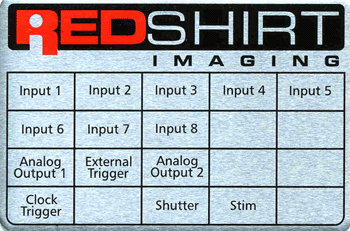
 

Description: C:\MyRSI\website\web 2010\site_build\support\images\icon_redarrow.gifControl Box

This unit is the external connection to the A-to-D board (DAP820/DAP840) and thus has the capacity of sending out TTL and other analog signals as well as accepting incoming signals.

Below is an image describing the inputs/outputs of this box. An equivalent image is glued to the top of every control box shipped by RedShirtImaging.

Description: C:\MyRSI\website\web 2010\site_build\support\images\ControlBox0001.gif
Description: C:\MyRSI\website\web 2010\site_build\support\images\blank.gif


Inputs 1-8 :

These 8 BNCs are intended for input of electrical data (Voltage, Current etc..) to be recorded in synchrony with the optical data. Connect the output from your amplifier(s) to any of those inputs. The inputs are digitized at 12 bit accuracy.


Clock Trigger:

The output from this BNC is a trigger to the camera for each frame acquired. This trigger is essential to the data acquisition and should be connected to the camera controller. (see diagram ).


Shutter:

Connect this BNC to the "Pulse Input" BNC on your Shutter Control Box and set the later to "remote control" (Names relate to the Uniblitz shutter control and might vary). The data acquisition module of NeuroPlex controls the shutter via this output.


Stim:

Connect this BNC to the "External trigger" of your stimulator. Any delay desired between the start of recording and the stimulus should then be set on your stimulator.


The following 2 functions are available for systems that have a DAP840 (but not DAP820) A-to-D cards (1) (2)

Analog Output:

Any signal sent by the NeuroPlex data acquisition function "Analog Output", will be output through this BNC. Thus - in order to send a voltage command or a waveform - this BNC should be connected to the appropriate external input on your amplifier.


External Trigger:

The purpose of this BNC is to synchronize the data taking with an external event (e.g. heartbeat, sniffing, EKG). When using the "external mode" (see software manual), after the "Start" button has been pushed, the program looks for an input voltage (2.5V or more) at this BNC to trigger the acquisition. The width of a repetitive triggering pulse should be shorter than the acceptable jitter in the relationship between the recorded event and the trigger. If the trigger signal is long (e.g. a duty cycle of 50%) different trials will be triggered at different phases of the cycle.


(1) To determine the type of DAP card you have see: NeuroCCDsm Hardware

(2) If your system was shipped prior to October 2001 you might have to make the connections inside the box for these 2 functions. See: NeuroCCD-sm Hardware