|
|

All
content |
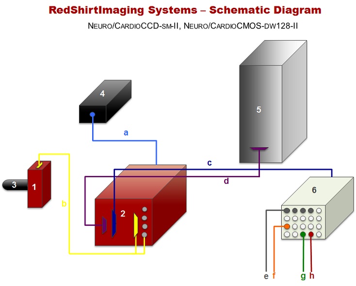
Components:
Connections: a - Power supply to camera controller. b - Cable connecting the camera head and the controller. c - Camera controller (AtoD) to control panel . d - Camera controller to EDT board. e - 4 analog BNC inputs. f - External Trigger. g - TTL output that controls the shutter or LED during data acquisition. h - short TTL output that triggers stimulator during acquisition.
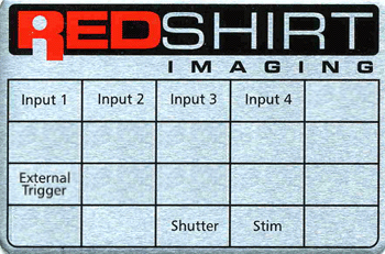
This
unit is the external connection to the AtoD board and
thus has the capacity of sending out TTL and other analog signals as
well as accepting incoming signals. Inputs 1-4 : These 4 BNCs are intended for input of electrical data (Voltage, Current etc..) to be recorded in synchrony with the optical
data. Connect the output from your amplifier(s) to any of those inputs.
The inputs are digitized at 12 bit accuracy. Shutter: Connect
this BNC to the "Pulse Input" BNC on your Shutter Control Box and set
the later to "remote control" (Names relate to the Uniblitz
shutter control and might vary). The data acquisition module of NeuroPlex controls the shutter via this output. Stim: Connect
this BNC to the "External trigger" of your stimulator. Any delay
desired between the start of recording and the stimulus should then be
set on your stimulator. The
purpose of this BNC is to synchronize the data taking with an external
event (e.g. heartbeat, sniffing, EKG). When using the "external mode"
(see software manual), after the "Start" button has been pushed, the
program looks for an input voltage (2.5V or more) at this BNC to
trigger the acquisition. The width of a repetitive triggering pulse
should be shorter than the acceptable jitter in the relationship
between the recorded event and the trigger. If the trigger signal is
long (e.g. a duty cycle of 50%) different trials will be triggered at
different phases of the cycle.
|
|||||||||||||||||||||||||||||||||||||||||||||||||||||||||||||||||||||||||||||||||||||||||||||||||||||||||||||||||||||||||||||||||||||||||||||||||||||||||||||||||||||||||||||||||||||||||||||||||||||||||||||||||||||||||||||||||||||||||||||||||||||||||||||||||||||||||||||||||||||||||||||||||||||||||||||||||||||||||