|
|
|
All
content |
Check the Line Voltage on the Power Supply Check the label
next to the power connector. It should be 110v for US and
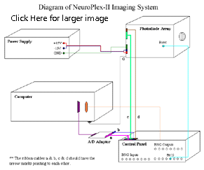
Connecting the Power Supply to the Diode Array Identify the power cables from the diode array. They are two groups (two wires in each group) of thick speaker wire. In one group two wires are connected to one spade connector, labeled with green tape. These are the ground wires. They should be connected to the green plug of the power supply. In the second group there are two spade connectors labeled with red and black tape. These are + 15v and - 15V cables and should be connected to the red connector and black connector on the power supply. When you are finished making the connection, use an Ohm meter to check these power connections. The red connector of the power supply should be connected to the connector on the diode array labeled +15V and the black connector on the power supply should be connected to the connector on the array labeled -15V.
After this check, put the switches on the diode array in the following positions:
Next turn on the power. The two lights on the power supply should be on. If one of them is not on, turn off the power immediately and contact WuTech. The power supply has an over-current protection and the light off indicates a short circuit. When power is on the two lights on the diode array should also light. This means the power is working properly. Before shipping, the power module and the diode array were powered (burned-in) for more than 100 hours and checked again. If a short-circuit occurs, it is likely that the connection is wrong or the polarity is reversed.
Connecting the Computer, A/D Converter / Interface Panel With the computer off connect the three cables from the interface panel to the computer. Connect the two DIP connectors to the MicroStar card in the computer via the small adapter piece (MSCBL 072-02) and the short cable. There are keys on these connectors to ensure the correct polarity of these three cables. However, the two DIP connectors (40 lines and 10 lines) can be forced to the wrong polarity. The 25 pin D connector should not be connected to the Serial port on the computer. It should be connected to the 25 pin D connector that is in the slot next to the connector on the Microstar a-to-d converter card.
Turn on the computer and watch the four lights at the center portion of the panel. These four lights should light, indicating the connection is correct and the panel is getting power (+,- 15V and + 5v) from the A/D converter. If any of these lights are off, contact WuTech.
Take data using the following procedure: Install the IDL dongle on the printer port of the computer. Click on the NeuroPlex icon on the Windows NT screen to run NeuroPlex. When the NeuroPlex window is opened, use Setup >> New Page and Trace Screen Size to make the Page and Trace screens have the desired size. Do Acquire >> Photodiode Array >> Number of Points so that the trace duration is about 1 sec. Then Go >> OK >> Start to take data. Some of the LED indicators on the left side of the panel should blink according to the data acquisition sequence. This indicates the computer, the program, the A/D card, and the Output-control panel are working properly. Next use a signal generator to provide a known signal of about 50 Hz to one of the BNC inputs on the right side of the panel. Take data again. Using Page Display >> Traces, you should see the appropriate signal on one of the BNC traces on the upper left and right of the Page Display window. This indicates that BNC inputs are working properly.
Connecting the Diode Array Mount the diode array on the microscope. If it is mounted horizontally, the C-mount will not be strong enough and additional support is needed. If the diode array is mounted vertically, no additional support is needed.
Connect the shielding ground of the diode array to the metal enclosure of the computer. A flat silver cable attached to the enclosure of the diode array is used for this connection.
Use an ohm meter to determine if the diode array is grounded to the microscope and the surface of the vibration isolation table. If the array is electrically connected to the microscope/isolation table, additional ground wires may be needed to tie all the large metal objects (microscope, arc lamp, manipulator and X-Y translation stages) on the vibration isolation table to a common ground point on the table top. This grounding procedure is similar to the grounding for electrophysiology. If the set-up is already good for local field potential recordings, the additional grounding procedure will probably not be needed.
With the computer off, connect the two ribbon cables from the diode array to the top connectors of the interface panel. The cables from the bottom connectors go to the computer (see above). The top and bottom connectors are not equivalent. There are keys on these connectors to ensure the correct polarity of these two cables. However, they too can be forced into the wrong polarity.
Use a BNC cable to connect the RESET output bit on the control panel and the RESET input on the Photodiode array.
Note for Zeiss Axioscope 2FS microscope users: The 1 X optic coupler/tube (part number 45 61 05) for mounting CCD camera (small 30 mm camera port) comes with a removable ring (field stop), which blocks a large portion of the visual field.
Testing the Photodiode Wiring Project the image of a pinhole (size ~1/10 of the field of view) onto the fiber aperture. The field diaphragm of the condenser can be used for forming such a pinhole. Let the microscope light pass through the pinhole and project on the array. The intensity should be set such that you can see it as a bright light but not very bright.
Connect the third output line, #2, (going from 0 to 7 from the left) to a stimulator which controls a shutter. Set up the stimulator to open the shutter after a delay of 50 msec for a duration of 50 msec. Do Acquire >> Photodiode Array >> Number of Points so that the trace duration is ~150 msec, long enough to record the shutter opening and closing. Then Go >> OK >> Start to take data. Using Page Display >> Traces, you should see square steps on many detectors and they should be in the shape of a circle. Using the centering adjustment screws on the substage condenser move the spot of light to various positions on the array and check that the circle moves appropriately and keeps a nice shape.
Dark Noise Measure the dark noise with a filter setting of 1 kHz and using the fastest acquisition rate (1.3 usec). In addition to determining the size of the dark-noise by measuring its RMS value, determine its frequency content by using the FFT option under Trace. There should be little or no line frequency (or harmonics) noise as well as no increase at high frequencies (which would indicate oscillations). A flat spectrum is good.
Inspect For Bad Channels Illuminate the diodes approximately evenly using an out of focus pinhole and shutter (see above). Take data and examine the Page Display screen to look for diodes that do not respond or which are excessively noisy. Typical systems have 5 or fewer bad channels. If you find more than five it is possible that the cards in the photodiode array box are no longer properly seated. Very carefully remove the top of the diode array and check to see that all of the cards are properly seated. Carefully replace the top of the diode array. (You can use either the Fudge Array or the Omit Array to replace the bad detectors with data from surrounding detectors or with flat lines.)
This is the final step of the installation. Important hardware limitations can be found in Support Issues: NeuroPDA-II Hardware Limitations. NeuroPDA Control Panel Outputs:
The pulses from
these bits should appear on an oscilloscope as follows: Congratulations and enjoy the new system. Jiang-young Wu, Ph.D. Chun Falk, Ph.D. |
|||||||||||||||||||||||||||||||||||||||||||||||||||||||||||||||||||||||||||||||||||||||||||||||||||||||||||||||||||||||||||||||||||||||||||||||||||||||||||||||||||||||||||||||||||||||||||||


