RedShirtImaging, LLC. NeuroPlex Photodiode Array Imaging System
Hardware Limitations

Description: Description: Description: http://www.redshirtimaging.com/support/images/cornerpinkffcfd2_ul.gif

Description: Description: Description: http://www.redshirtimaging.com/support/images/blank.gifDescription: Description: Description: RedShirtImaging Home

Description: Description: Description: http://www.redshirtimaging.com/support/images/cornerpinkffcfd2_ur.gif


SOFTWARE


Description: Description: Description: http://www.redshirtimaging.com/support/images/x.gif

  NeuroPlex

  Turbo-SM


Description: Description: Description: http://www.redshirtimaging.com/support/images/x.gif

  DownloadDescription: Description: Description: http://www.redshirtimaging.com/support/images/blank.gif


HARDWARE


  NeuroCMOS-DW


  NeuroCMOS-DW


  NeuroCCD-SM/SMQ


  NeuroCCD-SM256


  NeuroPDA-III


  MacroScope-II & -IIa


  Shutter


  NeuroPDA


Description: Description: Description: Description: Description: Description: Description: Description: Description: Description: http://www.redshirtimaging.com/support/images/icon_reddot.gif Installation

Description: Description: Description: Description: Description: Description: Description: Description: Description: Description: http://www.redshirtimaging.com/support/images/icon_reddot.gif Hardware Limitation

Description: Description: Description: Description: Description: Description: Description: Description: Description: Description: http://www.redshirtimaging.com/support/images/icon_reddot.gif Arrey Numbering

Description: Description: Description: Description: Description: Description: Description: Description: Description: Description: http://www.redshirtimaging.com/support/images/icon_reddot.gif Warning


*****************


Minimizing NoiseDescription: Description: Description: http://www.redshirtimaging.com/support/images/blank.gif


Ask The Expert


*****************


INFORMATION


Description: Description: Description: http://www.redshirtimaging.com/support/images/icon_reddot.gif

Contact Us


Description: Description: Description: http://www.redshirtimaging.com/support/images/icon_reddot.gif

Users


DISTRIBUTORS


Description: Description: Description: http://www.redshirtimaging.com/support/images/icon_reddot.gif

Australia, New Zealand


Description: Description: Description: http://www.redshirtimaging.com/support/images/icon_reddot.gif

British Isles, Benelux, France, Italy, Scandinavia, and Spain


Description: Description: Description: http://www.redshirtimaging.com/support/images/icon_reddot.gif

China, Hong Kong


Description: Description: Description: http://www.redshirtimaging.com/support/images/icon_reddot.gif

Japan


Description: Description: Description: http://www.redshirtimaging.com/support/images/icon_reddot.gif

Switzerland


Description: Description: Description: http://www.redshirtimaging.com/support/images/icon_reddot.gif

Taiwan


Description: Description: Description: RedShirtImaging Home


Description: Description: Description: http://www.redshirtimaging.com/support/images/cornerpinkffcfd2_ll.gif

Description: Description: Description: http://www.redshirtimaging.com/support/images/blank.gif

Description: Description: Description: http://www.redshirtimaging.com/support/images/cornerpinkffcfd2_lr.gif


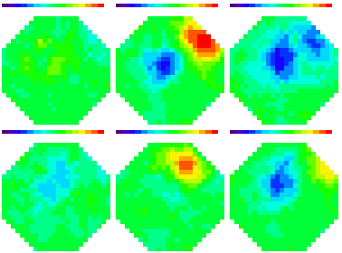
Propagating population signal from the turtle visual cortex. Provided by Jim Prechtl, Larry Cohen and David Kleinfeld, Yale University and UCSD.

All content
copyright © 1995-2002
RedShirtImaging, LLC.
Website Design by
Elizabeth Nephew

Unexpected Results
Occasionally (perhaps once a day or once a week) the camera will get in a strange mode and the images and values will be unexpected. First, try restarting NeuroPlex. If that doesn't solve the problem, try rebooting the PC and cycling the camera power. If it is convenient you might start each day with a PC reboot.
Don't use DC setting
Do not use the DC mode on the WuTech panel. Instead use AC with TC1 and TC2 turned to off. The time constant with this setting is so long as to be essentially equivalent to DC.
Low-pass filter settings
Use the low-pass filter settings on the WuTech panel from 50 to 1000 Hz. Using settings outside this range may not give the indicated frequency response.
Cross-talk
A multiplexer channel with an open input will always pick up signals from neighboring channels. You can expect to see this if you unplug second stage amplifiers from the multiplexer or if one of the BNC channels is left open and is adjacent to one that has a signal. The BNC cross-talk can be eliminated by grounding all inputs that are not used.

During testing using a step of light that is too large (it saturates some channels) will cause a very large crosstalk between channels.

There is always some crosstalk between channels even if no channels are saturated. Keeping the amplifier gain small (but large enough so that the noise is digitized well) will minimize this crosstalk (< 5%). Because this level of crosstalk is generally less than the noise in the measurement, we have never detected it in a real experiment.

Powering Up and Down
The multiplexer may be damaged if the amplifiers are on and the multiplexer is off. Turn off the amplifiers before shutting down the computer. Turn on the computer before turning on the amplifiers. One way to achieve most of this is to leave the computer on continuously. Turn the amplifier gain down to 1X before turning off the amplifiers.
 
Watch the Signal Size
Keep an eye on the size of the signal with no digital filtering. If the minimum and maximum value in traces differ by 5000 mv, then it is likely that some amplifiers will be saturated which can cause trouble in other amplifiers. Reduce the second stage gain to keep the difference in the range of 2000 mv.
Amplifier Drift and Settling
  • Amplifier drift is difficult to detect with either AC1 or AC2 turned on. However with both off, in the Pseudo-DC mode, some channels will have a drift as large as 100 mv/second at a gain of 1000. This fits with the rule that there is no such thing as a drift­free amplifier. This amount of drift usually is not a severe limitation.
  • Amplifier Settling. At the beginning of data acquisition (following the end of the reset pulse) there is a settling transient (100 mv at a gain of 1000) with AC1 or AC2 on. This transient lasts about 100 msec. You can keep this out of the data by setting "Time for Amp Adjust" to 100 msec.
  • This amplifier drift and settling, which occurs in the dark, is often smaller than drifts and settlings from other sources (e.g. interference filter equilibration, dye bleaching, lamp drift).

     
    Acquisition Rate
    For long trials (> 8192 data points) the maximum sustained data acquisition rate is a SAMPLE INTERVAL of 21. This limitation can be removed by obtaining a new version of the data acquisition board.
    Green Grounding Terminal
    In typical installations this grounding terminal is not used. If line-frequency noise is detected, try connecting this ground to other grounds in the apparatus.